Hardware Design Criteria Maker Faire “Mini Supercomputer”
Once we settled on the basic components that the system would contain, the hardware almost designs itself. Classic issues of computer design are heat and power. We also wanted it to look “cool”, preferably showcasing internal components, and as many blinking lights as possible. We want to be able to individually power up and down the 4 processors, the network, and any fans used for cooling. (This implies 6 toggle switches.) We also hate noise, so want any fan usage to be minimal.
So, we thought of some sort of transparent case, and the obvious choice is an acrylic tube. Extruded acrylic tubes are reasonably priced in 6 foot lengths. Our system uses a 16 inch length of 5 inch diameter tubing. One of the challenges is getting a straight cut on a large tube like that. We gave the tube to a woodworker friend, and came back a few days later to an (almost) perfect cut.
Obviously, hot air rises, so the simple cooling solution is a fan at the bottom of the tube, with an open top. We used these really nice forged copper heatsinks on the Raspberry PI systems, and the Parallella systems came with their own beefy heatsinks. We also provided real time clock daughter cards for the Raspberry PI systems, so we could keep track of time without being connected to the network. We planned for no network connection at the Faire. We had to clip some of the pins so they would fit in the tubular case.
For our internal ethernet switch, we chose the Trendnet TEG-S5G ethernet switch. Cheap, gigabit ports, runs on 5 Volts from it’s power adapter. Very easy to remove the single small circuit board from it’s case, and install in our system
Inspired by the Cray 1 and the Apple G4 cube, we planned, then, a small rectangular box, out of which would rise vertically the acrylic tube holding the processors. All we had to do was figure how to put it all together.
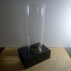
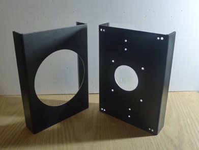
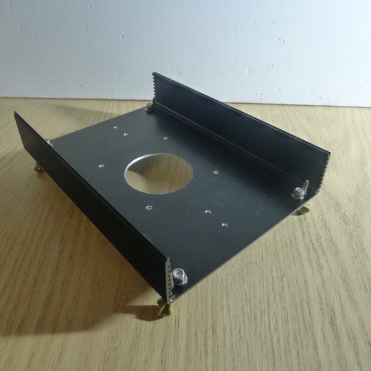
We found a nice candidate box to serve as the base at Fry’s. A nice matte black sturdy anodized aluminum case from a company called Context Engineering. (model 6016H-8.5B) The technological challenge here was to create a large hole in the top so that the acrylic tube could fit snugly, and a similar hole in the bottom through which air could be drawn for the cooling. Bought a large circular hole drill bit at Lowes, left the stuff with woodworker friend, came back a few days later to the perfect top hole. Did the bottom hole with a pattern of circular small holes, followed by chiseling and hand filing. The result, including mounting holes etc, is:
UNDER CONSTRUCTION, TO BE COMPLETED June 9-16, 2017
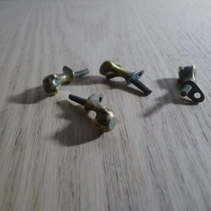
Since the cooling air will be pulled in from the bottom of the case, we needed some way to lift the case to provide an air gap. We realized we were going to have a bit of a “steampunk” look once we started looking at the toggle switches we’d chosen for the front panel. Looking on the web for some sort of cast brass feet that would be in keeping with that look, we stumbled upon these wonderful cast brass “Griffin’s Feet”. After the acrylic tube and the Parallella systems, these were probably the most expensive component. They work great and look fabulous:
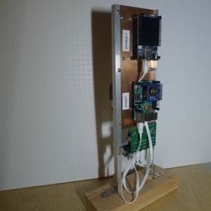
How do we mount the 4 systems and the ethernet switch so that they can then be enclosed by the acrylic tube, and still be accessible for repair/tweaks etc. The answer was to make a sort of “tower”. We used two appropriately lengthed extruded aluminum “L” channels, with a sheet of copper between them to provide a nice flat surface for mounting components. The copper sheet also provides thermal equilibrium, and a nice ground plane. We purchased a sheet of “hobby” copper from our local hardware store, which was 4 inches by 10 inches. The size was perfect, and we used it without modification. Like all the fasteners in our system, we used a variety of stainless steel nuts, bolts, and washers, always with a split washer to provide a durable connection. We are a big fan of boltdepot.com, and would tend to “overbuy” nuts and bolts in quantities of 100, giving us a nice base of parts for many future systems to come. We like to use stainless steel nuts and bolts both because they are so strong, and like the look.
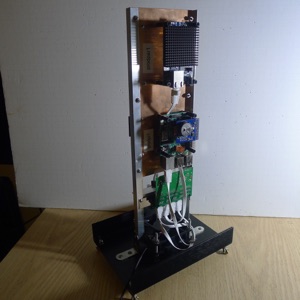
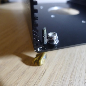
Here’s what our “cpu tower” looks like outside of the box. It terminates on the bottom with two stainless steel “L” brackets that bolt onto the 4 longitudinal, slight offset, mounting holes in the bottom of the case.
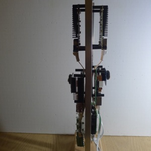
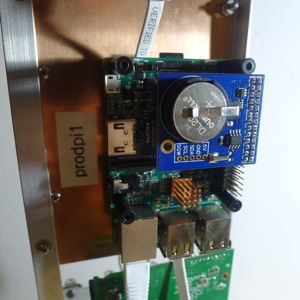
Here’s some close up photos of the “tower”, showing the placement of the various parts. On the left is one of the two Raspberry PI systems. We have labelled it “prodpi1”. Remember there is it’s twin, “prodpi2” mounted on the other side of the copper sheet. We used simple bolts and nylon standoffs to give a little space to the copper sheet. You can just see the smaller of the two copper heatsinks we used. Clearly visible is the blue RTC daughter-card. Its uses a large CR-2032-type lithium button cell for power. We expect these batteries to last at least a year. We discuss how to integrate the RTC usage with the system in the software section. Below the Raspberry PI is the ethernet switch. (The green circuit board.)
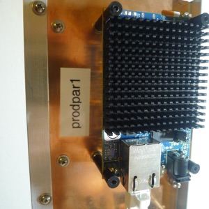
On the right photo below is one of the Parallella systems. (“prodpar1”) They ship with the large heat sink that one installs oneself. This is the minimal system, which really only has ethernet and power ports as access to the external world. Both of these can be seen below the heat sink. Again, there is it’s twin (“prodpar2”) mounted on the backside of the copper sheet. We used higher nylon spacers for these cards. The idea was to maximize the free flow of air.
We determined the precise placement of the cards and mounting points essentially by trial, error, and eyeball. The amazing thing about the 4-inch wide copper sheet is that it almost perfectly spans a standard 3.5 inch computer case cooling fan. You’ll see how we took advantage of this later.
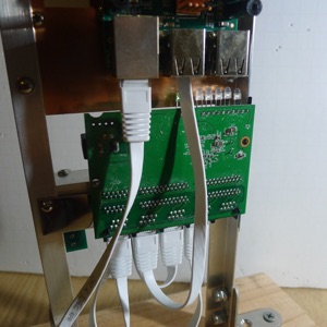
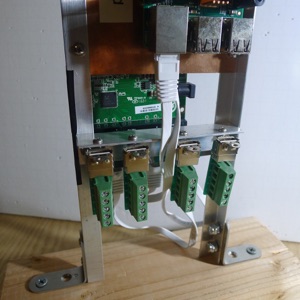
Continuing closeup views of our “tower”, we now show the backside of the ethernet switch circuit board, and the mechanism we used to provide power to the systems. On the left below is the backside of the circuit board of the ethernet switch. We made a little bracket that bolts to the two vertical uprights, and then the board is attached to the bracket with very strong double sided mounting material. On the right, is another bracket we attached to the uprights, with 4 LCOM USBAFT parts bolted to it. The LCOM parts provide a socket for 4 USB cables which are used to carry power to the systems from simple screw-tightened connections for bare wire. (Our power distribution turned out to be very inefficient. Please note an extensive discussion of this at the end of this page.)
The two “L brackets” at the bottom of the two uprights are clearly visible. Fasteners connect these directly to the bottom plate of our system box.
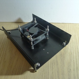
As promised, on the lower left photo is the installed fan for cooling. We configured it to move air “up”, since that’s the natural thing for hot air to do. We’ve just used a standard 3.5 inch computer case fan. Probably worth it not to buy the cheapest fan, since better bearings will mean a quieter, more efficient experience. One could use a 12 volt fan, running on 5v, or a 5v “native” voltage fan. We use a 5 violt “native” unit. Event he slightest air-flow should be sufficient for cooling.
On the lower right, our “tower” has been installed, As we discussed, the 4 inche copper sheet is almost the perfect size to straddle the fan unit. (We had to allow about a 1/16 inch extra space each side on the bolting together.)